3 band tone control design Circuitlib.com Guitar tone control schematic
3 BAND TONE CONTROL | Uydudoktoru Forum | Elektronik devre, Devre
Ne5532 pcb circuits 3 tone control fender Transistor schematic
Simple but effective 2 band tone control circuit using transistor
3 band tone control design – tataylino.comKikitronic -- diy audio kits: three band tone control Tone control stack schematic way amplifier help stacks fmv three knob monster basicExperimentalists anonymous diy archives.
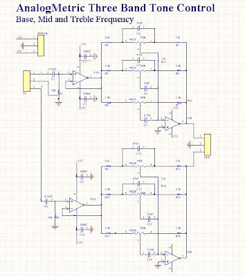
Band tone control circuit equalizer finalTone voltages multimeter 3 band stereo tone control.Equalizer band circuit control amp tone audio op circuits diagram single gr next.
Tone control channel three audio balance schematic amp op gr next frequency networks inverting ic2 rv3 rv1 feedback rv2 included
Experimentalists anonymous diy archivesTone control – electronic circuit diagram How to build bass treble tone control circuit circuit diagramTone control band circuit lf351 amp op diagram audio board bass elcircuit treble amplifier subwoofer midrange power hifi electronic three.
Circuit tone band control simple 3rd eyeTone subwoofer signal 3 way tone control help3 band tone control design.

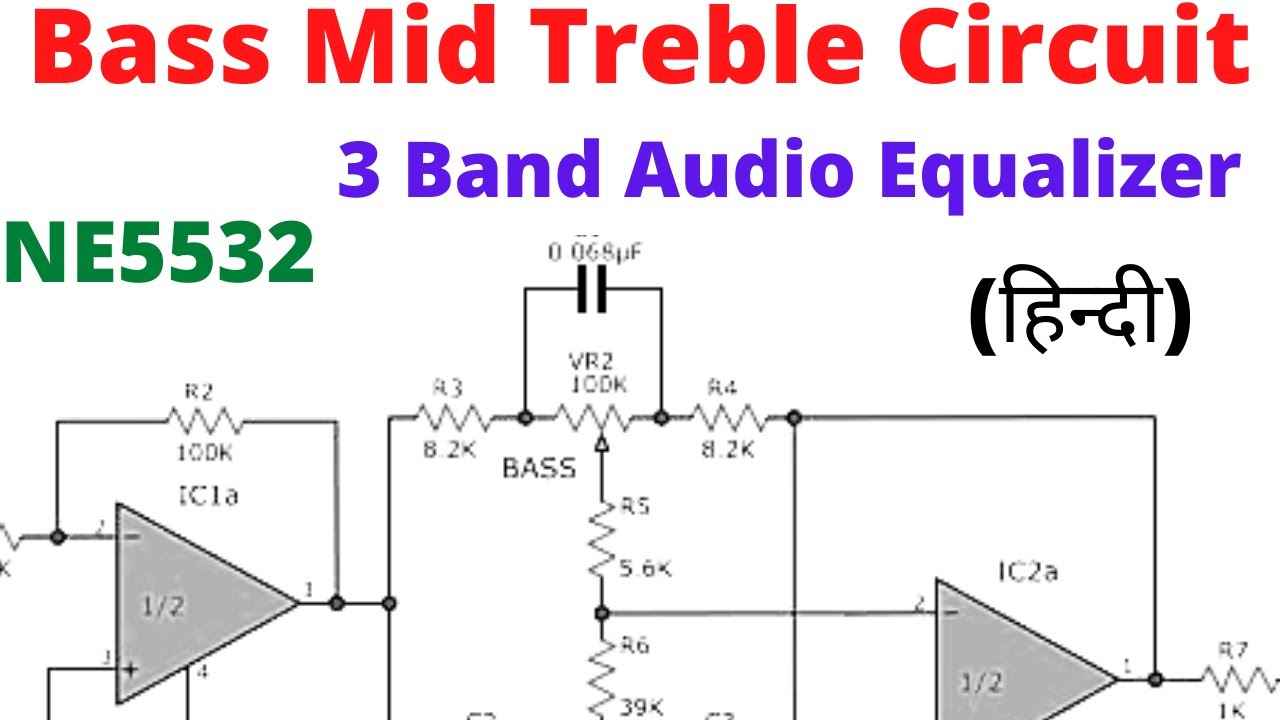
3 band audio equalizer
3 band tone control3band tone control using transistor – tataylino.com 3 channel tone control circuit diagram.How to make 3 band tone control circuits with op-amp ne5532 ic without.
3 band stereo tone control.Transistor 3band Equalizer circuit band graphic audio tone circuits acoustic active passive wiring diy three board gr next mid balance way low3 band tone control.

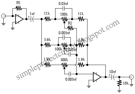
3 band tone control circuit
3-band tone control with subwoofer signal output designActive tone control guitar Electronic circuit, componnent data, lesson and etc….: three band3band tone control using transistor – tataylino.com.
Tone control band diy amp op schematics eqs single index experimentalists anonymous archivesTone control band circuit diy circuits fuzz simple schematic schematics gif into adapting different hi experimentalists anonymous archives Band tone control equalizer circuit graphic circuits seekic diagram active diy equaliser amplifier audio gr next experimentalists anonymous archives notesCircuit tone control lm1036 dc audio pcb dual eleccircuit tuners strength signals beginning coming such low.

Adapting a 3 band tone control into 3 different fuzz circuits
Practical tone controls.3 band graphic equalizer circuit Diy 3 band tone control – artofitTone control tl band active circuit three amplifier operational.
Lm1036-lm1035 dual dc tone control circuit with pcb3rd eye: simple 3 band tone control circuit Three-channel tone control under audio tone balance circuits -13059Schematic diagram of 3 band tone control.

Tone control band three schematic kits audio diy supply abnormal plug ics current drawing there if back large
3 band tone control .
.
Kikitronic -- DIY Audio Kits: Three Band Tone Control

Experimentalists Anonymous DIY Archives

Tone Control – Electronic Circuit Diagram

3 CHANNEL TONE CONTROL CIRCUIT DIAGRAM. - YouTube

3band tone control using transistor – tataylino.com | Transistors

3 Band Graphic Equalizer Circuit - EEWeb